
(Pickups) by Kurt Prange
Passive (i.e. battery-free) electric guitar circuits are relatively simple and the possibilities for customization are endless. A basic understanding of pickups, potentiometers, capacitors and switches is all you need to get creative and take more control of your instrument’s voice on an electronic level.
Where does the electric guitar signal come from?
Pickups are transducers that convert the mechanical energy of a vibrating guitar string into electrical energy by way of electromagnetic induction. It is a fundamental concept studied in physics and electronics that a changing magnetic field will generate a current through a coil of wire. The electric guitar pickup uses permanent magnets and pole pieces to form a steady magnetic field in the vicinity of each individual guitar string. An opposite magnetic polarity is induced in the metallic (steel core) guitar string when mounted above its respective pole piece and when the string moves, the otherwise steady magnetic field changes accordingly. Wire is wrapped around the poles thousands of times to form a coil within the magnetic field to pick up an induced current and voltage.
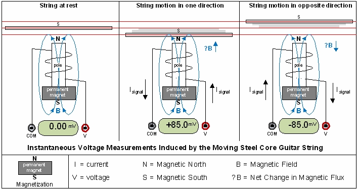
The output signal from the pickups is AC (alternating current) because the direction of the current alternates, producing a positive voltage when the string moves in one direction and a negative voltage when the string moves in the opposite direction.
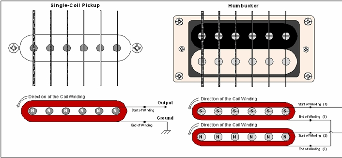
The previous drawing illustrates the electrical and magnetic function of a single-coil pickup. Some pickups might use six permanent magnets in place of the six pole pieces to create the magnetic field, but the idea is the same: create a steady magnetic field around a coil in proximity to the guitar string. The name “single-coil” pickup becomes more significant when compared to the humbucker or “dual-coil” pickup.
Pickups: Single-Coil vs. Humbucker
The first successful guitar pickup was developed in the early 1930’s by Rickenbacker® to help amplify Hawaiian lap steel guitars which were popular at the time. The first pickups were single-coils and while they do a good job of picking up the guitar signal they are also susceptible to picking up interference from nearby electrical devices. The Gibson® humbucker (US Patent 2896491) was developed in the 1950’s to eliminate the “hum noises” resulting from electromagnetic interference. The humbucker uses two coils and a pair of pole pieces (having opposite magnetic polarities of each other) for each string. The coils are wound and connected to each other in such a way that the current produced by the moving guitar string in the two coils adds up (in-phase), while the current produced by electromagnetic interference in the two coils cancels (out-of-phase). Not only does the humbucker drastically reduce noise from interference, but it also has a different characteristic sound. The single-coil pickup is commonly considered to have a thin, clear and bright (more treble) sound, while the humbucker is known to have a full, but dark (less treble) sound with more overall signal output.
Connecting Multiple Pickups
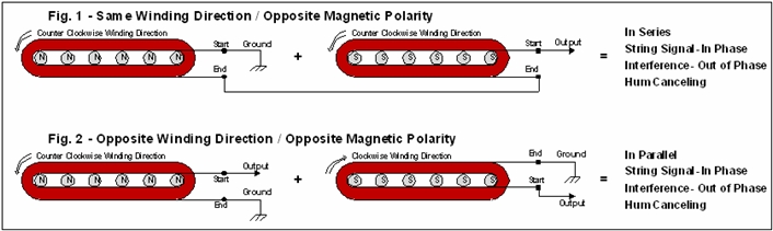
When connecting more than one pickup, it’s important to follow the manufacturer’s color codes and wiring diagrams so that the phase relationship is correct. The phase relationship of a pickup is determined by the winding direction of the coil and the polarity of the magnets. The two coils of the traditional humbucker are connected in series with the phase relationship shown in Fig. 1. Most modern Stratocaster® style guitars with three single-coil pickups are supplied with a reverse wound/reverse polarity middle pickup for a parallel hum canceling effect when the guitar is switched to a two pickup position (e.g. neck & middle pickup together) as shown in Fig. 2.
Pickup Specs
Most replacement electric guitar pickups have limited electrical specifications given on the packaging or on-line which can give you a basic idea of the relative output level and how bright or dark a similar pickup will sound.
• DC Resistance: This can be measured directly with an ohm meter and gives you an idea of how many turns of wire the coil has. If the same gauge of wire was used for two pickups, then the pickup with fewer turns to the coil will have a lower resistance which, in general, makes for a lower output level and a brighter sound.
• Inductance: Inductance is the ability of an inductor (or coil) to store energy in a magnetic field. A higher inductance makes for a higher output level and a darker sound.
• Peak Frequency: This is the frequency beyond which the output level begins to fall dramatically. A higher peak frequency would make for a brighter pickup.
Variety is the spice of tone.
Guitar pickups are a vital component of your tone and replacing them is something that most guitarists can learn to do themselves. Using high quality pickups can go a long way to bringing new life and excitement to your playing experience. There are hundreds of pickup manufacturers and thousands of pickups to choose from. Whether you’re looking for a hotter pickup, trying to capture a beloved vintage tone or seeking single-coil sound in a noiseless package, brands like DiMarzio®, Seymour Duncan®, Lace®, Porter®, Fender®, Gibson® and many others offer a solution.
Potentiometers and Tone Capacitors
What is a Potentiometer?
Potentiometers, or “pots” for short, are used for volume and tone control in electric guitars. They allow us to alter the electrical resistance in a circuit at the turn of a knob.
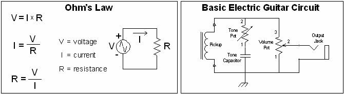
It’s useful to know the fundamental relationship between voltage, current and resistance known as Ohm’s Law when understanding how electric guitar circuits work. The guitar pickups provide the voltage and current source, while the potentiometers provide the resistance. From Ohm’s Law we can see how increasing resistance decreases the flow of current through a circuit, while decreasing the resistance increases the current flow. If two circuit paths are provided from a common voltage source, more current will flow through the path of least resistance.
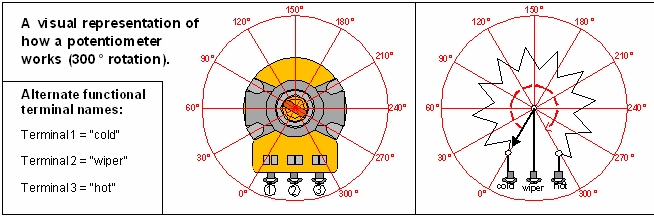
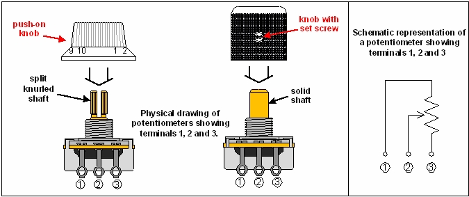
We can visualize the operation of a potentiometer from the drawing above. Imagine a resistive track connected from terminal 1 to 3 of the pot. Terminal 2 is connected to a wiper that sweeps along the resistive track when the potentiometer shaft is rotated from 0° to 300°. This changes the resistance from terminals 1 to 2 and 2 to 3 simultaneously, while the resistance from terminal 1 to 3 remains the same. As the resistance from terminal 1 to 2 increases, the resistance from terminal 2 to 3 decreases, and vice-versa.
Tone Control: Variable Resistors & Tone Capacitors
Tone pots are connected using only terminals 1 and 2 for use as a variable resistor whose resistance increases with a clockwise shaft rotation. The tone pot works in conjunction with the tone capacitor (“cap”) to serve as an adjustable high frequency drain for the signal produced by the pickups. The tone pot’s resistance is the same for all signal frequencies; however, the capacitor has AC impedance which varies depending on both the signal frequency and the value of capacitance as shown in the equation below. High frequencies see less impedance from the same capacitor than low frequencies. The table below shows impedance calculations for three of the most common tone cap values at a low frequency (100 Hz) and a high frequency (5 kHz).
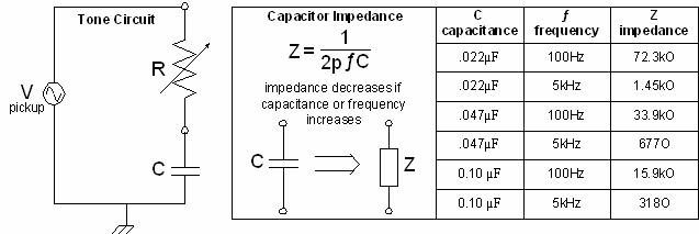
When the tone pot is set to its maximum resistance (e.g. 250kΩ), all of the frequencies (low and high) have a relatively high path of resistance to ground. As we reduce the resistance of the tone pot to 0Ω, the impedance of the capacitor has more of an impact and we gradually lose more high frequencies to ground through the tone circuit. If we use a higher value capacitor, we lose more high frequencies and get a darker, fatter sound than if we use a lower value.
Volume Control: Variable Voltage Dividers
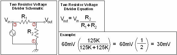
Volume pots are connected using all three terminals in a way that provides a variable voltage divider for the signal from the pickups. The voltage produced by the pickups (input voltage) is connected between the volume pot terminals 1 and 3, while the guitar’s output jack (output voltage) is connected between terminals 1 and 2. From the voltage divider equation below we can see that if R1 is 0Ω and R2 is 250kΩ, then the output voltage will be equal to the input voltage (full volume). If R1 is 250kΩ and R2 is 0Ω, then the output voltage will be zero (no sound).
Potentiometer Taper
The taper of a potentiometer indicates how the output to input voltage ratio will change with respect to the shaft rotation. The two taper curves below are examples of the two most common guitar pot tapers as they would be seen on a manufacturer’s data sheet. The rotational travel refers to turning the potentiometer shaft clockwise from 0° to 300° as in the previous visual representation drawing.
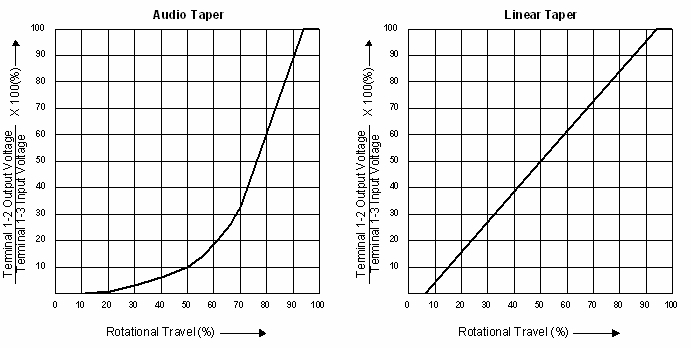
How do you know when to use an audio or linear taper pot?
It’s really a matter of personal taste when it comes to volume control. Notice how the rate of change is much more dramatic on the audio taper pot when traveling back from 100% to 50% rotation. This means that the same amount of rotation would give you a more intense volume swell effect with an audio taper than with a linear taper. Using a linear taper volume pot would give you a more gradual change in volume which might feel like you have more fine control with which to ease back the volume level.
For tone control, it’s basically standard practice to use an audio taper. The effect of the tone circuit is not very noticeable until the resistance gets pretty low and you can get there quicker with an audio taper.
How do you know what value of potentiometer to use?
The actual value of the pot itself does not affect the input to output voltage ratio, but it does alter the peak frequency of the pickup. If you want a brighter sound from your pickups, use a pot with a larger total resistance. If you want a darker sound, use a smaller total resistance. In general, 250K pots are used with single-coil pickups and 500K pots are used with humbucking pickups.
Specialized Pots
Potentiometers are used in all types of electronic products so it’s a good idea to look for potentiometers specifically designed to be used in electric guitars. If you do a lot of volume swells, you’ll want to make sure the rotational torque of the shaft feels good to you and most pots designed specifically for guitar will have taken this into account. When you start looking for guitar specific pots, you’ll also find specialty pots like push-pull pots, no-load pots and blend pots which are all great for getting creative and customizing your guitar once you understand how basic electric guitar circuits work.
(Switches and Output Jacks)
Now let’s take a look at how pickup selector switches and output jacks work.
Pickup Selector Switches
Most guitars have more than one pickup and each one has unique tonal characteristics depending on its placement, construction and materials. The pickup selector switch allows the guitar player to choose between different pickups or a combination of them. The pickup placed close to the guitar neck has a warm, smooth tone with more bass content and is frequently referred to as the “rhythm” pickup, while the pickup placed close to the bridge has a sharper, biting sound with more treble content and is frequently referred to as the “lead” pickup. Of course, these are just generalizations. You might find that the neck pickup sounds sweeter for your leads or maybe you get more rhythm crunch from the bridge pickup. The subjective nature of tone is one of the main reasons it’s empowering to be able to customize your own instrument.
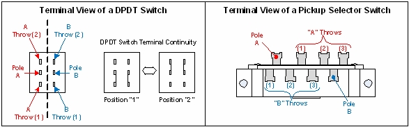
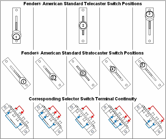
People are often confused by the switch terminology of “poles” and “throws”, but it’s actually quite simple. The switch allows us to change the electrical continuity between its terminals. The “pole” is the name of the terminal whose continuity is switched between one or more throws. As shown in the DPDT (double pole double throw) switch drawing above, in position “1” there is continuity between “Pole A” and “A Throw (1)”. In position “2” there is continuity between “Pole A” and “A Throw (2)”. This A-side alone could be thought of as an SPDT switch because it has a single pole with two throws, but because we have an additional B-side the entire switch has two poles with each pole having its two respective throws (i.e. DPDT). The standard Telecaster switch could be considered DP3T because it has two poles with each one having three throw terminals. The standard modern Stratocaster switch adds two intermediate switch positions “2” and “4” (as shown below) where each pole has electrical continuity with two of its respective throw terminals at once.
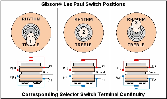
The standard Les Paul switch is shown below. In position “1” P(A) has continuity with T(A), but P(B) is disconnected from T(B). In position “2” both P(A) and P(B) have continuity with their respective throws T(A) and T(B). In position “3” P(B) has continuity with T(B), but P(A) is disconnected from T(A). The ground terminal is used to connect to the common ground along with the potentiometers, output jack and the bridge in order to eliminate popping and buzzing noises.
The Output Jack
The output jack allows us to connect the signal from the guitar to an amplifier. The standard guitar output uses a ¼” mono jack having two terminals (as shown below) which make contact with the mono ¼” plug end of the guitar cable. The “tip” terminal is connected to the output signal and the “sleeve” terminal is connected to the guitar’s common ground. This is standard for amps and effects pedals, too.
Wiring Diagrams
It’s easy to find electric guitar wiring diagrams on-line through the websites of guitar and pickup manufacturers. There are also a lot of popular modifications out there that you might like to try out. Once you understand the basics of how these circuits work, you can even get creative and customize an original circuit that suits your style best. You won’t have to feel locked into your standard set up ever again. If you come across a new trick that you think you might like, heat up your soldering iron and try it out.
article from:
Kurt Prange (BSEE) is the Sales Engineer for Amplified Parts in Tempe, AZ. Kurt began playing guitar at the age of nine in Kalamazoo, MI. He is a guitar DIY’er and tube amp designer who enjoys helping other musicians along in the endless pursuit of tone.
Document for print here: Basic electric guitar circuits
